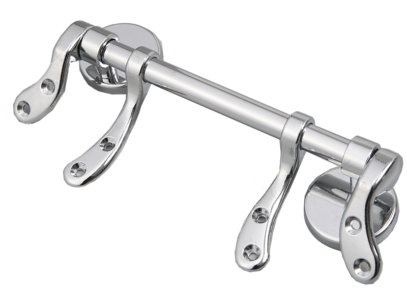
Generally, the upper lid and seat of the toilet are hin […]
Generally, the upper lid and seat of the toilet are hinged with the toilet body through a hinge. After people use it, if the toilet lid or toilet seat is not gently put down by hand, the toilet lid or toilet seat will collide with the toilet body. A lot of noise can also cause damage to the toilet seat or toilet lid. For this reason, a toilet cover with a damping mechanism is designed. This damping mechanism is assembled by a fixed connection method, which is difficult to assemble. At the same time, the toilet cover has a single fixing structure, which makes it difficult to disassemble and assemble the toilet cover, especially in the later maintenance of the toilet cover. Therefore, a toilet cover that can realize the quick disassembly and assembly function of the toilet cover The board fixing device has considerable market prospects.
1. The fixed structure of the new toilet cover, including the support, the foot, the lowering device, the push rod, the fixing piece, the spring, the push block, and the fixing pin; the fixed sleeve of the fixing piece is placed in the middle of the inner cavity of the support, inside the lowering device The end is fixed and sleeved in the inner cavity of the support, the upper end of the fixed pin passes through the side hole on the support and then is sleeved in the fixed hole of the reverse descender. The lower end of the fixed pin is fixed on the foot so that the reverse descender will not rotate. , The outer end of the push rod extends outwards with a card, the card gap is inserted into the inner end hole of the reverse descender, and is clamped in the slot at the upper end of the fixing pin that penetrates into the fixed hole of the reverse descender, the inner end of the push rod It has an oblique sliding block and the oblique sliding block movably penetrates into the inner cavity of the fixed part in the longitudinal direction, and the push block is moved in the horizontal direction through the through hole in the middle of the support and then penetrates into the fixed part. The push rod inserted into the fixed part is slidably connected to the sliding block, the push block is fixed in the fixed part, and the spring is arranged between the push block and the fixed part.
2. A guide bar is provided on the top of the push rod, and a guide groove is provided in the inner cavity of the fixing member. The guide bar on the top of the push rod is slidably connected to the guide groove of the inner cavity of the fixing member.
3. There are two sets of anti-droppers, push rods, feet, and fixed pins; the two sets of push rods and anti-droppers are respectively sleeved on both sides of the fixed part.
4. It is characterized in that it includes a seat ring and an upper cover. One ends of the seat ring and the upper cover are sequentially fixed and sleeved on the outer end of the reverse descender.
5. The card slot on the outer wall of the reverse descender is sleeved on the card strip in the inner cavity of the support; the push block is provided with two inclined sliding grooves, and the two inclined sliding grooves are arranged symmetrically; the missing groove in the button is buckled on the pushing block The inner end of the push block is provided with an inverted buckle, which can be buckled on the cross bar in the middle of the fixing member for fixing the push block.
6. There is a guide groove on the top of the fixing member, which is slidably connected to the clip in the inner cavity of the support, so that the fixing member will not rotate; including anti-skid pads, which are fixedly installed on the feet.
Related Suggestion : Hinge-J-QA

